- Catalogues
- Fire Damper
- Fire/ Smoke Damper
- Air Control Damper
- Installation Drawing
- Suggested Specification
|
|||
|---|---|---|---|
Fire Damper (防火閥門) |
|||
|
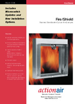
FIRE/SHIELD Stainless Steel Bladed Curtain Fire Dampers Series |
|
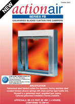
SERIES FB Galvanised steel bladed curtain fire dampers |
| Smoke/Fire Damper / Smoke Extraction Damper ( 防火及防/排煙閥門 ) | |||
|
SMOKE/SHIELD Proportional Torque Control - Automatic Smoke and Fire Dampers |
|
HOT/SHIELD High operating temperature smoke management and fire dampers |
| Air Control & Shut- Off Damper ( 空氣調節閥門 / 閉氣閥門 ) | |||
|
AIR/SHIELD Control and Shut Off Dampers |
 |
Energn/SHIELD ES Control and Shut Off Dampers |
 Actionair with 30 years of market experience is acknowledged as UK market leader in the manufacture of top quality fire, smoke and air control dampers and waterside control fan coil units, serving buildings in Britain and throughout the world.
Actionair Fire/Shield - Stainless Steel Bladed Curtain Fire Dampers Series |
|||
|---|---|---|---|
|
|
||
| Catalogues | Construction |
||
|
|
||
Actionair SERIES FB - Galvanised steel bladed curtain fire dampers |
|||
|
|
||
| Catalogues | |||
New Cassette Specification |
|||
|
|
||
Actionair Smoke/Shield PTC - Proportional Torque Control - Automatic Smoke and Fire Dampers |
|
|---|---|
|
|
| Catalogues | Construction Smoke/Shield PTC™ |
|
|
|
Control Options |
|
|
Approvals |
|
|
|
Actionair Hot/Shield - High operating temperature smoke management and fire dampers |
|
|
|
| Catalogues | Construction Hot/Shield PTC™ |
HKFSD No-objection Letter |
|
Approvals |
|
|
|
|
|
Multiple Assemblies for Actionair Smoke/Fire and Fire Damper |
|
 Actionair has always been at the forefront in the innovative development, design and manufacture of life safety dampers and associated controls. Now with the unique Smoke/Shield PTC™ range of Automatic Smoke and Fire Dampers Actionair continues this tradition.
 Actionair have developed the Hot/Shield PTC™ High Temperature Smoke Management and Fire Dampers along with the Hot/Shield Vent PTC™ Smoke Control and Extract Dampers to enable the concepts of fire engineering to be employed in ducted smoke ventilation systems.
 Advanced Thermal Enclosure
Actionair Air/Shield Control and Shut Off Dampers |
|
|---|---|
Catalogues |
The Air/Shield range of quality engineered dampers are suitable for air conditioning and ventilation systems requiring air control and low closed blade leakage characteristics, for standard low/medium pressure and velocity systems. |
Size Variations |
|
 |
|
Air/Shield Features and Design Guide Opposed blade dampers suitable for systems requiring air control (Aerofoil) and low closed blade leakage (Aeroseal). Suitable for low/medium pressure and velocity systems. Available in flanged type casing up to 1000mm square or spigotted type casings up to 1000mm square / 1000mm diameter or flat oval up to 1000mm x 500mm in a single drive arrangement. |
Series Aerofoil |
Series Aerofoil Series Aerofoil for system air balancing having aerodynamic ribbed double skin type 1.4016 (430) Ferritic Stainless Steel 50mm wide x 0.4mm thick blades. Housed within a galvanised mild steel flanged or galvanised spigotted casing being suitable for systems with a temperature range of –20 °C through to +70 °C. |
|
Series Aeroseal |
|
Series Aeroseal for system air balancing and shut-off having aerodynamic double skin type 1.4016 (430) Ferritic Stainless Steel 50mm wide x 0.4mm thick blades with synthetic trailing edge blade seals and Stainless Steel side seals. Housed within a galvanised mild steel flanged or galvanised spigotted casing being suitable for systems with a temperature range of 0 °C through to +70 °C. |
|
Specification for AIR / SHIELD DAMPERS |
|
 |
The casing shall be either galvanised frame with peripheral flanges prepunched with elongated corner hole fixing to suit proprietary duct flanges (type FLA) or double skin spigot casing with square, rectangular, circular of flat oval connections (type SPG). Complying to the requirements of DW 144 Classes A, B and C. Air balancing dampers (vcd) shall have low profile aspect ratio aerofoil stainless steel opposed blades with positive cap and bar drive mechanism totally enclosed and out of the air stream. Control dampers shall have low profile aspect ratio aeroseal stainless steel opposed blades with silicone treated, synthetic blade seal and spring stainless steel peripheral gasketing to minimise air leakage in the fully closed position with the air flow in either direction. The blades are driven through 90 degrees with the gearbox and positive cap and bar drive mechanism totally enclosed and out of the air stream. Control dampers shall be suitable for systems having a maximum differential pressure of 1000 Pa and shall have a maximum closed blade leakage of 25 l/sec/m² at this pressure. All manually operated balancing dampers shall have positional indicators and locking devices. Motorised dampers, where required, the motors shall be factory fitted and tested with a simple push fit direct to the damper drive without the use of couplings or linkage and selected to give the required torque rating. |
Actionair Energy/Shield ES35 & ES36 Control and Shut Off Dampers |
|
Catalogues |
ES35 and ES36 Features and Design Guide |
-
Fire dampers shall be installed on the Drawings and at locations required by the FSD. All fire dampers shall be tested to ISO10294 Classification E with hot air leakage not exceeding 360 m³/hr/m² at differential pressure of 300 Pa and approved by the Fire Services Department. FSD ‘no-objection’ letter shall be submitted for each type of fire damper to be used.
-
Fire damper blades shall be of the 0.71mm stainless steel grade 316 curtain type with the stainless steel spring loaded blades housed out of the air stream, to reduce pressure drop and noise regeneration. Dampers shall have a rigid and air-tight all continuously welded casing constructed from 1.22mm galvanized steel sheet and be complete with installation frame.
-
Fire damper shall be released by HKFSD approved one-hand resettable automatic locking device with thermally reusable shape memory metal coil rated at 69°C for the convenience and reliabilty of periodic testing.
-
Spring tempered stainless steel gasketing shall be inserted between the blade edges and the casing to prevent jamming and spread of smoke.
-
Manufacturing of dampers shall comply to BS5750 or ISO9002 quality assurance scheme.
-
Proprietary access doors of adequate size shall be installed adjacent to each fire damper and in the case of conditioned air or kitchen exhaust ductwork, the access doors shall be incapsulated and preinsulated.
-
Each fire dampers shall be complete with proprietory made installation frames providing clearance for thermal expansion.
-
Power fail-safe remote electro magnet release shall be provided to explosion hazardous areas. The electromagnet shall normally not consume more than 10mA by 240V AC supply or 120mA by 24V AC/DC supply. All the electrical components of the unit will be located outside from the hazardous environment in a water proof box. The Sub-Connection shall be responsible for the power fail-safe from the fire control relay at the fire services control panel to close fire dampers within 1 second. All necessary materials and control cables shall be provided by the ACMV Sub-Contractor.
-
Fire dampers shall be rated in accordance with the fire rating of the “wall” of “floor” in which they are installed.
-
Combination fire/smoke dampers shall be tested to ISO10294 classification ES with hot air leakage not exceeding 200 m³/hr/m² at differential pressure of 300 Pa and UL555S Cl. 1 and approved by the Fire Services Department. Dampers shall be furnished by a manufacturer who has produced dampers of similar construction for a period of at least 10 years in the proposed manufacturing plant and with the proposed product with at least 5 years of satifactory experience of similar size in Hong Kong.
-
The dampers shall be of be wholly stainless steel grade 316, aerofoil bladed construction with the blades held in stainless steel bearings and framed in stainless steel spring tempered flexible gasket.
-
The blades shall have trailing edges forming and interlocking metal to metal seal when the blades are closed providing tight, low leakage closure of the air path and maximum impedance to the passage of smoke and products of combustion from either flow direction.
-
The blades shall be driven by externally mounted totally enclosed stainless gearbox and drive mechanism of the same manufacturer providing accurate blade control with minimum torque and without accumulative backlash.
-
The damper casing shall be of double skin galvanized steel construction with continuously welded corners and integral spigot connections. The dampers shall be supplied complete with proprietary installation frames.
-
Each damper shall have an externally replaceable fail-safe electric thermal sensor with tested rating of 68°C completely exposed to the air stream.
-
The damper shall be normally held by electromagnet with power consumption not more than 3W and released to the closed, or fail safe position on loss of power supply, either by genuine power failure where the system is not on essential power or by the zone fire signal actuated by the smoke detection system.
-
The damper shall automatically reset by build-in proportional torque driving motor of 240V AC or 24V AC/DC on resumption of mains supply, unless the fire signal has been received, where remote reset shall be given. The whole control mechanism shall be of the same manufacturer and mounted inside a totally enclosed casing for protection against airborne contaminants.
-
For application at fire extinguishing gas flooding system in harzardous environment, damper shall be released within 10 sec. by an electrothermal link with manual reset mechanism located remotely at non-harzardous location.
-
For dynamic smoke extraction application, damper control actuator shall be totally shielded by a proprietary thermal insulation casing. Dampers shall be tested to ISO10294 classification ES with hot air leakage not exceeding 200 m³/hr/m² at differential pressure of 300 Pa and UL555S Cl. 2. The whole damper-actuator assembly shall be undergone a high-temperature operation test at 250 °C for 1 hour and followed by a leakage test at 1500Pa differential pressure test and ultimately approved by HKFSD.
-
All air handling unit and ductwork regulating dampers shall be of the aerofoil, double skin, opposed blade type with low pressure drop and noise regeneration characteristics.
-
Individual blades shall be coupled by means of metal gears from a single operating spindle suitable for motorization or hand operation. The mechanism shall be located outside the air stream. A lockable quadrant shall be provided for hand operated dampers.
-
Blade shall be constructed by 0.91mm Stainless Steel surfaces of double skin construction encapsulating an internal double 1.22mm contoured steel longitudinal reinforcing bar.
-
Bearings shall be nylon materials and the units shall be of low-leakage design by incorporation of synthetic trailing edge seals and a peripheral gasket which should be tested according to BS476 part 6 and 7 and approved by HKFSD.
-
All dampers shall have rectangular flange, circular or flat oval spigot connections as required.
-
For system static pressure below 1000 Pa or duct velocity below 12 m/s, width of blade at least 50mm shall be used. For static pressure at or above 1000 Pa, at least 100mm shall be used, and central blade reinforcement bar shall be provided for damper span longer than 1500mm. Single module of a damper shall not exceed 2000mm width and 1000mm height.
-
All dampers shall be sufficiently rigid to prevent fluttering. Unless otherwise indicated the air leakage across dampers in the fully closed position shall not exceed 30L/S/M2 at 1000Pa differential pressure of the maximum design air flow in the duct.
-
For dampers for shut-off purpose, the maximum leakage shall be 9L/S/M2 at 2000Pa differential pressure.